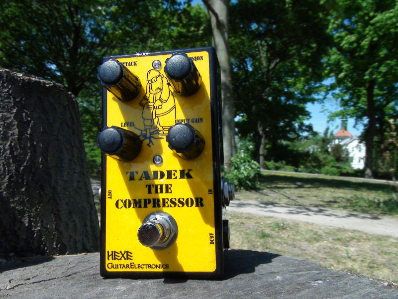
Easy to build (no internal adjustments required), nice sounding compressor for bass and guitar.
Pedal utilizes the TDA7052A 1W BTL audio amplifier chip with volume control as VCA and phase splitter for the full wave envelope detector. Might be an interesting alternative to compressors based on the obsolete CA3080 OTA.
Design:
Back around 2010 Elektor published a project of a compressor pedal, similar to the CA3080 Ross Comp, but using the TDA7051A as an alternative, since the CA3080 was already discontinued. I have tried that circuit on a breadboard, but was not really satisfied with the results. The gain of the TDA chip was set too high resulting in high noise levels. Nevertheless it was an inspiration, which pushed me to design my own approach for a TDA7052A based gutiar/bass compressor.
After doing more tests i discovered, the lowest noise i could get from the design was when the TDA chip is at unity gain when idle and used only as an attenuator. The additional gain, or make up gain will have to be provided by a separate gain stage.
The topology used in the design is a feedback compressor, meaning it is the amplitude of the output signal that is controlling the gain. 7052A, being also a BTL (Bridge-tied load) amplifier has a complementary outputs delivering signals with opposite phase. Perfect to drive the side chain part of the circuit.
Let's take a look at the schematic:
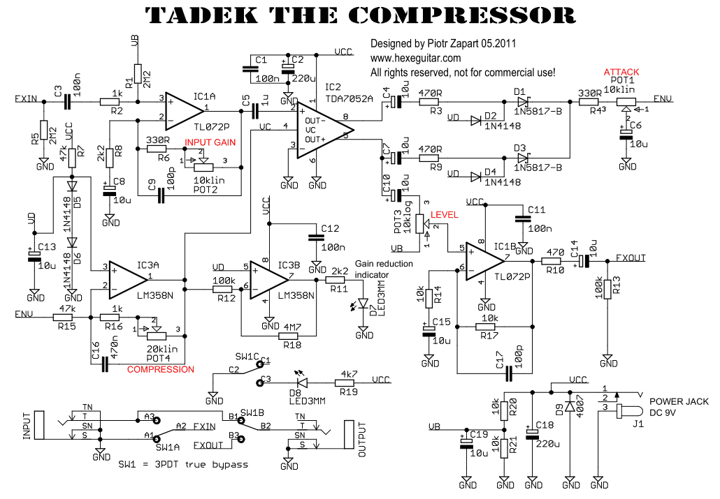
The fist stage made with a half of the TL072 opamp provides a high input impedance and boosts the signal to be able to drive the 7052A chip and achieve a good s/n ratio. The INPUT GAIN control allows to adjust the gain depending on the instrument type the pedal is used with. A Strat guitar with single coils pickups will definitely need more gain than an active bass humbucker. This pot sets also the compression threshold.
Before we follow the audio signal further, let's see how the idle or max gain (attenuator, remember?) of the TDA chip is set. It is a constant bias voltage, around 1.2V, produced by the combo of R7 + D5 and D6, which though the IC3A is applied directly to the VC input of the TDA7052A. The VC input is quite sensitive, hence i had to make the bias voltage VD independent of the VCC supply voltage, which might vary. To make it simple, a voltage drop of two silicon diodes did the trick.
Ok, we have the main gain controller chip set to about a unity gain and it outputs the audio signal in two copies with opposite phases. We can use them to drive a full wave rectifier and an envelope follower. Since it's an audio amplifier chip, the output impedances are extremely low. Driving the rectifier and the output IC1B stage is not a problem. R9 (470R) makes it even easier.
The full wave rectified signal is run through a simple RC lowpass filter (R4 + 10k Attack Pot + C6) and fed into the inverting input of the IC3A. At this stage, the envelope signal is scaled and subtracted from the previously mentioned VD - a constant bias voltage setting the idle gain, thus creating a variable attenuation. That's how the compression mechanism works.
Audio signal is taken from the non inverting output of the TDA7052A and, through a LEVEL pot fed into the output make up (2x) gain stage. The output stage provides low and constant ouput impedance.
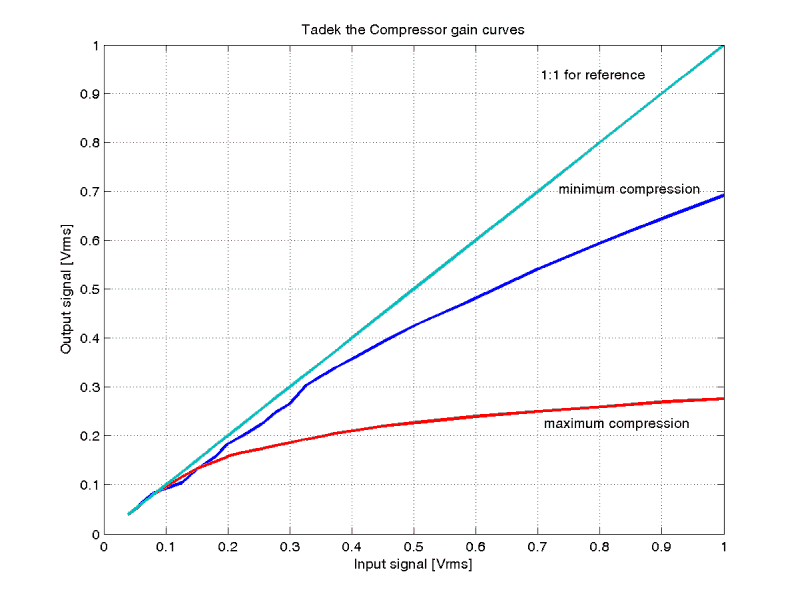
Below are the measured gain curves with COMPRESSION control set to minimum and maximum.
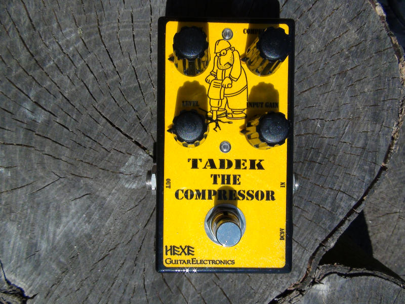
- Input Gain - use it to set the input gain according to the output signal of your instrument. Use lower settings for active electronics and humbuckers and higher gain for single coils. This knob controls the compression threshold.
- Compression - sets the compression ratio. A yellow LED diode is used to show the amount of compression (kind of a gain reduction meter...).
- Attack - controls the reaction time of the compressor. In practice, this knob controls the amount of transients present in the compressed signal.
- Level - output volume control.
Power requirement: 9VDC 25mA.
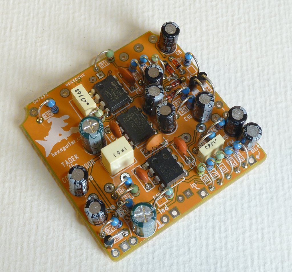
Build:
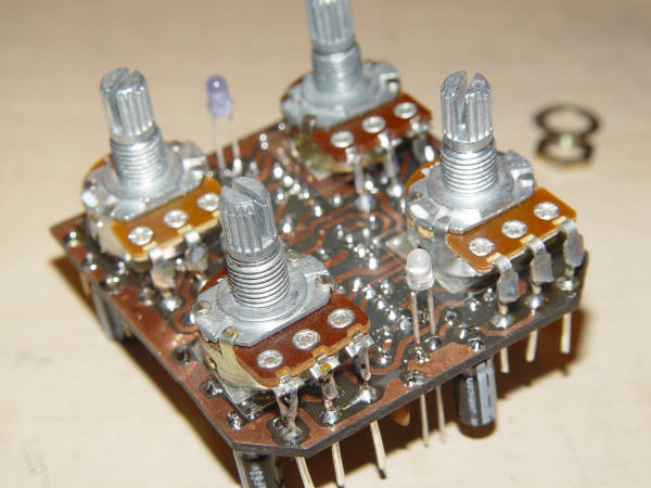
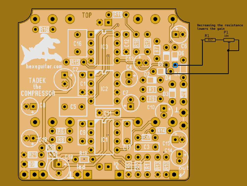
PCB is designed to fit into a typical 1590B enclosure. All the components are through hole, potentiometers are mounted on the back side of the PCB.
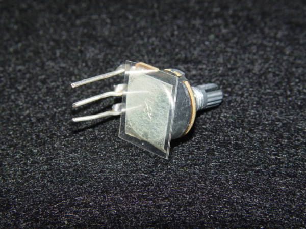
Put a piece of insulating material or use one of those insulating caps for pots to avoid shorting the pads om the PCB.
Pots already mounted on the PCB. The easiest way to make it correctly is to:
- Install the pots, but do not solder them in yet.
- Install the PCB into the enclosure and screw in the pots.
- Now, solder in the pots.
- Unscrew the pots and do the rest of wiring.
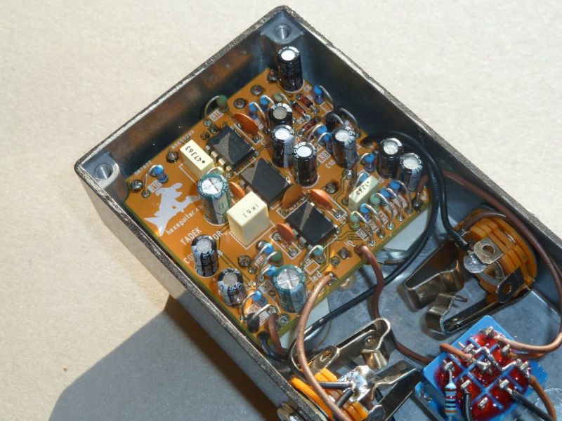
Wiring complete:
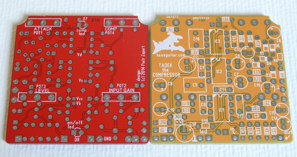
Manufactured PCBs:
I still have a few of these fabbed PCBs, please contact me if you are interested in getting one.
Mods:
Sometimes, especially when using the pedal with instruments with hot pickups it might be necessary to lower the idle gain of the TDA7052A, otherwise the signal will be clipped even at minimum Input Gain settings. To achieve that you can use this simple mod: just put a 4k7 resistor in series with a 10k trimpot between the VB point and GND. The trimpot will decrease the bias voltage and lower the idle gain of the stage.
Media:
Design files are available in the github repository:
https://github.com/hexeguitar/Tadek-Compressor
Click to open in new window
git clone https://github.com/hexeguitar/Tadek-Compressor- Home

- DIY
- Guitar Gear
- Tadek the Compressor