
Tiny compact current, voltage and power meter module that will help you while designing and troubleshooting circuits.
The module utilizes the TI INA219B high side current sensor chip and a PIC24F16KA101 microcontroller to read out and display the data. Besides the meter function, the PCB can be used as a simple PIC24F16KA101 development board.
Project background/idea:
Why bother to build such a device, when you could use a cheap multimeter or a bench power supply to do the same job?
- Small and compact size of the module (5x5cm not including the LCD). Standard 5.5/2.1 center negative power jacks make it perfect to plug it between the PSU and your circuit, build it into your power supply, use it as a current monitor in your pedalboard, etc.
- Highly tweakable architecture. By changing the value of the current sensing resistor and the INA219 interal calibration constants you can build many variations of the circuit, maintaining the relatively good measurement precision (12bit AD converter built into the INA219).
- Overcurrent ALARM FUNCTION - this feature may be extremely useful when debugging circuits, as the current consumption is often a much faster indicator of any possible malfunction. Ialarm (current threshold) value is set with a pot. When the alarm condition occurs (drawn current exceeds the threshold value) the module will kindly inform about that fact by blinking the current value and giving an acoustic signal. Please remember though, this is not a current limit function! It will only inform you that the current drawn by the circuit is more than you expected.
- Data logging feature. The module sends the measurement results via UART in 1 second intervals. The readout is available in two formats.
- Educational value. Besides being a useful bench tool, building the Power Monitor can be a good exercise in using the PIC24 microcontrollers, communication protocols (SPI, I2C), interfacing LCD displays and more. All the design files and the source code are released under Open Source Hardware license.
Basic application:
- Operating Voltage: 5 - 26V DC.
- Voltage measurement resolution: 10mV.
- Current sense range: 0 - 1A.
- Curent measurement resolution: 50µA.
- Power measurement resolution: 1mW.
- Alarm current range: 0 - 1A (pot set to max = alarm OFF).
- Low dropout input polarity protection.
- Reverse power jack protection (DCin and DCout swapped).
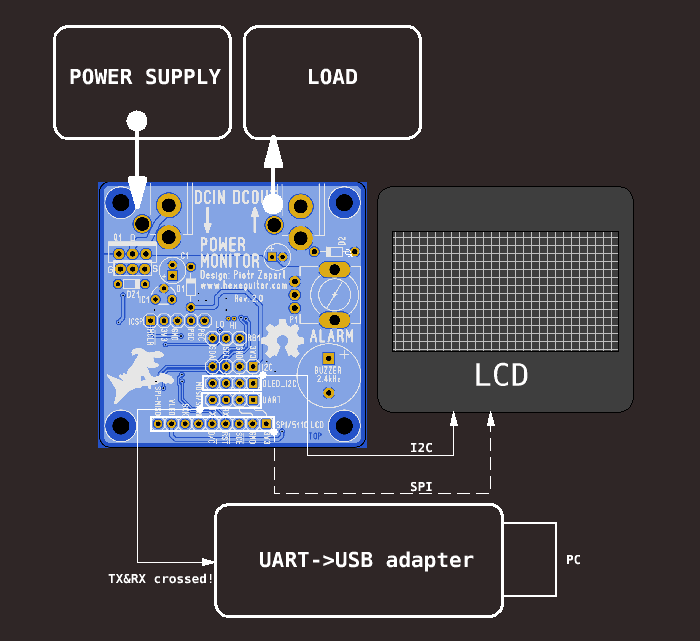
- 128x64 I2C 0.96" OLED display (SSD1306 controller chip).
- 84x48 SPI LCD (PCD8544/Nokia5110).
- Data readout via UART (9600baud, 8b, 1 stop bit, no parity).
- INA219 recalibration option via UART.
- I2C, SPI, UART and Microchip ICSP headers.
Build:
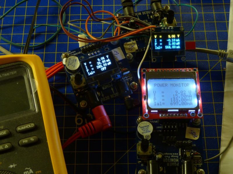
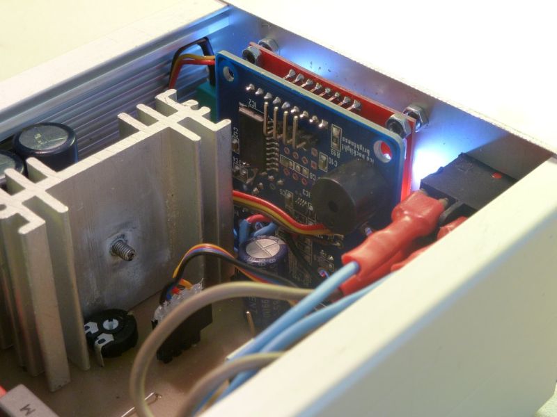
Partially populated PCB (bottom layer, all SMT parts).

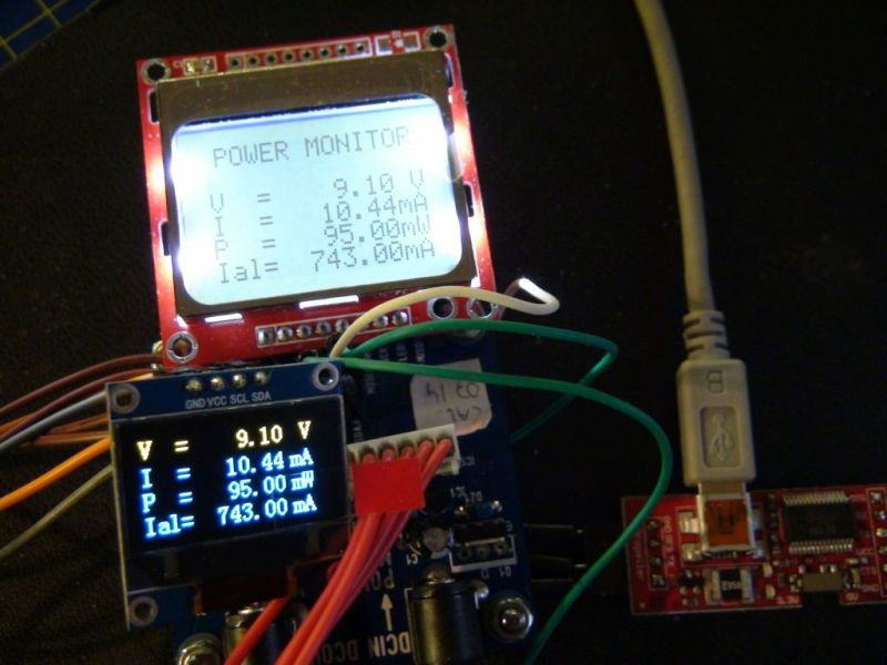
Two display types are already implemented in the firmware:
- 128x64 SSD1306 I2C driven 0.96" OLED
- SPI 84x48 PCD8554/Nokia5110 LCD.
Serial port (UART) is used to send the data to the PC (here via an UART-USB converter).
Measurement results are sent in two available formats: LCD (basically copy of the LCD screen).
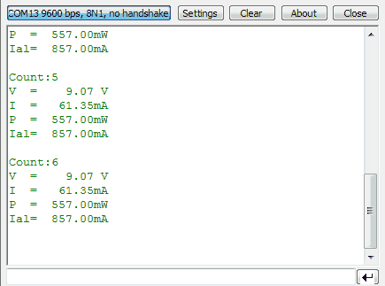
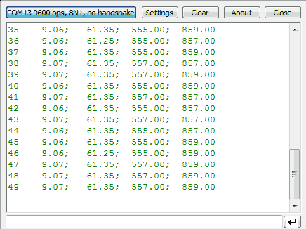
Or in RAW format, which is more useful for datalogging:
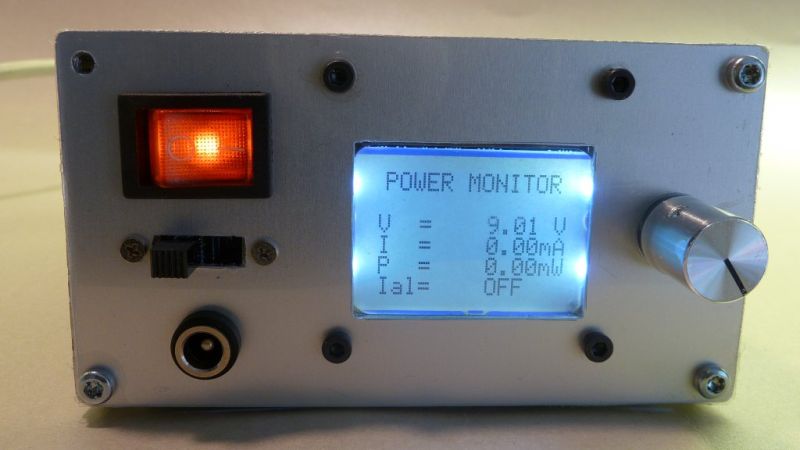
Module built into a power supply.
Design files are available in the github repository:
https://github.com/hexeguitar/PowerMonitor
Click to open in new window
git clone https://github.com/hexeguitar/PowerMonitor